Monday 6 December 2010

Week 47/48 of 2010

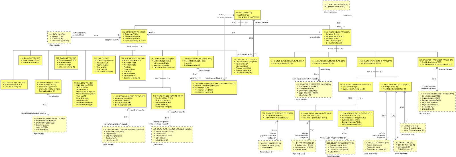
I've been working on the software architecture of the Chess Tool application for the last two weeks. I've also been trying to stay warm given the cold snap here in Colchester. I don't ever remember seeing snow in November before! Anyway, I going to discuss the Values subsystem of the software architecture in this blog. The latest OIM is given below:

The subsystem originally started off with a small set of data value subtypes but has expanded over time to include most of the data values defined in the Data Type subsystem of the OOA of OOA. However, I have discovered some issues with how I defined data values in the OOA of OOA which I will mention as I discuss each subtype below.

Undefined Value is implemented as a Java enum with a single UNDEFINED value. It is useful when dealing with generic values. However, it is not that useful generally since most assignment targets can (and should) be specifically typed. For example, a numeric value attribute will be typed as a NumericValue and if conditional then undefined is represented using null or an associated value status set to UNDEFINED.

Boolean Value is also implemented as a Java enum with FALSE and TRUE values. In my OOA of OOA, I also allowed users to define false and true aliases. However, on reflection that was a bad idea since Action Language code that uses the aliases can hide bugs where a user thinks an alias is TRUE when in fact it is actually FALSE. Instead, users should use enumerated values instead of aliased boolean values.

Enumerated Value design has undergone a number of iterations. The first requirement was to be able to map enumerated types/values to Java enum's which implement Specific Enumerated Type and Specific Enumerated Value interfaces. These values are associated with static enumerated type information allowing them to be used statically within generated code. I supplemented this with a Qualified Enumerated Value allowing a system dependent type to be associated with an enumerated value. However, such values can't be used statically within generated code. Later I added the concept of a Generic Enumerated Value which is enumerated type independent. It can be matched against any enumerated value with the same legal value name. However, generic enumerated values are not ordered and so can't be used in relational comparisons (unless a promotion to a typed value is possible).

Symbolic Value encapsulates Java String values. However, Java string length is based on 16 bit character counts for backwards compatibility, not Unicode character counts. I prefer to use actual Unicode character counts instead.

Numeric Value has numerous subtypes which have evolved considerably. They are shown on the OIM in promotion order from left to right. Automatic ID Value encapsulates non-negative Java int values (no time unit). Limited Integer Value encapsulates Java long values. Integer Value encapsulates Java BigInteger values. Decimal Value encapsulates Java BigDecimal values. Rational Value encapsulates a numerator/denominator pair allowing lossless division and the representation of negative zero, NaN, Infinity and -Infinity values. Rational Interval Value encapsulates a rational interval with a lower endpoint numerator, an upper endpoint numerator and a shared endpoint denominator. This is a more specialized numeric value not often supported in traditional programming languages.

The final subtype is Floating Point Value which encapsulates Java double values. Such values are normally approximate values since underflow and overflow is handled using approximation without user intervention. For this reason, all such values are prefixed with '~'. Once a numeric value is promoted to a floating point value, it is never narrowed without user intervention since all previous subtypes are assumed to be exact values while floating point values are assumed to be approximate.

All of the above subtypes handle negative zero consistently. However, whether a negative zero is preserved after been assigned to an assignment target (attribute, variable etc.) depends on the numeric type of that target. Most programming languages only handle negative zero in floating point arithmetic. However, I believe multiply and divide should be defined consistently across all numeric values, i.e. result sign is negative only and always if operand signs differ. However, negative zero is invisible when comparing numeric values. It only has a significant impact when it is used as a divisor resulting in a signed infinity (assuming dividend non-zero).

Rounding modes are associated with numeric types not numeric values. However, most programming languages perform rounding immediately when integer divide is performed. I prefer to promote the result of a division with a non-zero remainder to a rational value and leave any rounding to when the result is assigned to a target with an associated numeric type. Obviously, the remainder '%' operator doesn't make any sense without immediate rounding to determine the remainder, i.e. a lossless remainder operation always returns zero! Lossless (or lazy) division can have a significant impact on how code executes if the user assumes implicit immediate rounding. However, it should be possible for an analyst to change a numeric type without reworking Action Language code so inconsistent arithmetic rules across numeric types is something that should be avoided.

Numeric value also supports an optional time unit allowing duration values to be defined. This concept may be extended in future to support other unit types. However, allowing time units now helps develop an understanding of how units can be supported in the future. Subtracting a time from another time results in a duration. Performing arithmetic on two durations requires the duration time units to be the same. This can be done automatically except where one operand is DAY or smaller and the other is MONTH or larger since you can't convert durations between days and months outside the context of specific times.

Time Value is no longer a numeric value since most arithmetic operations don't make sense. Only subtraction of time values is allowed. I originally defined time values as numeric values in my OOA of OOA. An optional time unit is associated with time values so that when times are subtracted, the time unit of the resulting duration can be determined. The time unit is also used when converting time values into numeric magnitudes. Underlying time values are represented in UTC time relative to the Java Epoch ('1970-01-01 00:00:00'). An optional time zone is also associated with time values for determining calendar specific component values such as year, month, day etc. However, time unit and time zone are not preserved during assignment to a time typed target since that target will specify it's own preferences.

Handle Set Value allows object instance subsets to be represented. They are created from object instance lookups and relationship navigations. All non-empty handle sets are backed by the full set of object instances (which acts as the universal set) so that absoluteComplement() can be invoked on such values. Empty handle sets are another matter. A Qualified Handle Set Value allows backed empty sets to be created but such values can't be used statically since they are system dependent. That was why I introduced a Specific Empty Handle Set Value which allows an empty set to be statically defined for handle sets with specific object/class names. I also defined a Generic Empty Handle Set Value for situations where the object name is unknown. However, specific and generic empty sets have no associated universal sets so absoluteComplement() can't be applied to them.

I initially left handle sets unordered. However, most set operations (contains, union, intersection, difference) are much quicker when the sets are consistently ordered. To make consistent ordering possible, I now define a system-wide fixed ordered automatic ID literalID on all object instances. Such an ID is easy to allocate and defines a run-time ordering across all object instances. I also use this ID when formatting handle set literals. However, this ID is not persisted across runtimes.

Composite Value allows structured values to be created with readable but non-writeable components. Such values are discussed in xtUML02. I wasn't going to support composite values initially. However, they have immediate application as input/output parameter sets. They can also be used to create object instance snapshots when necessary. I don't currently allow composite values with no components.

List Value allows generic value lists to be created and iterated over. Such values should never be associated with attributes since they should never have a multiplicity of many. However, they may be created and passed as parameters or event data items since we allow a multiplicity of many on parameters in general. More commonly, they are useful within Action Language operation bodies where processing has been divided into stages. I'm not sure there are any benefits allowing other collection types (e.g. Bag, Set and OrderedSet) since their use is strictly temporary and localized.

I've run out of time so I won't go into predefined operations today or literal string syntax. Next time, I will also discuss the Types subsystem which sits above the Values subsystem.

Monday 22 November 2010

Week 39/40/41/42/43/44/45/46 of 2010

This weekly report is actually a two monthly report! I just haven't had much enthusiasm for blogging. However, apart from last week (I was up in Nottingham visiting relatives) I have been busy on the Chess Tool case study previously mentioned. Lets start with the domain chart:

I'm only showing the Shaler-Mellor diagrams here. However, I will write up the case study as a multi-notation technical note in the future given Executable UML versions of all diagrams. The application domain covers Chess rules and the playing of Chess games. I spend a couple of weeks immersing myself in the world of Chess. The current OIM for the Chess domain is given below:

I've also modelled the lifecycles of matches, human players and computer players but I don't want to overload this blog with too many diagrams. They will all be in the final case study report. I will also leave further discussion of the Chess model to the report since I want to overview my other progress. I haven't progressed the User Interface domain far yet since I'm fairly confident I can tackle it last.

I initially placed the XML based Persistence domain above the Software Architecture domain as a proper service domain. This is fine for formatting purposes. However, for XML parsing the domain starts to rely heavily on metamodel mappings. Since this would make the case study more complicated than necessary I decided to move persistence below the software architecture, i.e. it's now an implementation domain allowing the XML parser factory logic to be hand coded. The J2SE XML parser will now load initial XML files parsing them into DOM structures which will now be traversed with custom code resulting in the population of initial Chess and User Interface object instances. This kind of decision as to what domains will be code generated and which won't needs to be made with care. Ones that should be excluded will often involve integration with existing libraries. In this case, I'm taking advantage of the J2SE XML libraries to do the actual parsing. If I was going to implement the low level parser then I would have kept persistence as a service domain.

After I looked at the Persistence domain, I moved onto the Software Architecture domain. I'm been on this for many weeks now. My intention with this case study was to manually generate code (since OOA Tool doesn't support Archetypes yet). However, I still want to model the architecture and design archetypes to control the manual generation of this code. I've gotten carried away with this! I starting with Data Values (and literal syntax) and the predefined operations supported by these values, moved onto Data Types (and declaration syntax) and the validation processes involved, then onto system, domain, object, attribute, link and operation instances. I then started to instantiate Chess versions of object instances etc. so I can understand what needs to be generated by archetype templates in future. In parallel, I created simulated versions of object instances etc. that could be used to run a simulation within OOA Tool in future. Since then I have been experimenting with mixed generated/simulated code. Complicated operation instances can be hand coded while simple operation instances can use Action Language parsed expressions. The current OIMs for Values, Types and Instances are shown below:

All of the above has been implemented in Java using Eclipse which I've been using for the first time trying to put JBuilder to bed. I'm starting to wonder If I can implement a complete Action Language driven virtual machine here which I hadn't planned to do for this case study. I will have to see how things go.

My experience with Eclipse has been mixed. Refactoring is much more powerful than in JBuilder 2005, but search and replace across a project is pretty crap in Eclipse. Maybe there is a plugin somewhere that fixes this. I'm also finding the debugger difficult to use. Maybe it just takes time and I've gotten used to the JBuilder debugger. One thing that annoys me is that the cursor in Eclipse seems to jump about a bit opening windows unexpectedly. I think there are some bugs here. I will say using generics in Eclipse is a completely different experience than trying to use it in JBuilder which is badly broken in that area.

I've also been using the released version of OOA Tool Build 014 to create the Chess Tool models. I have discovered a number of bugs during this process that required me to hack the XML to fix a corrupted "ChessTool.ooa" file. If anyone has a similar experience then they should email me their model I will fix them for you. I don't want to return to OOA Tool development at this time but I will document the bugs I have found (and associated workarounds) in the future.

I've also been following the debate on referential attributes in the Executable UML forum but my yahoo account doesn't seem to be working properly - it doesn't recognise my email when I try to login, yet it's still forwarding me email updates - weird! Referential attributes are crucial to the Shlaer-Mellor and Executable UML experience in my opinion. However, I have found situations were cardinality limits beyond zero-one-infinity can be beneficial in a model without creating models susceptible to change, e.g. a binary relationship in the Shlaer-Mellor metamodel has exactly two participants by definition. I may allow such explicit cardinality constraints to be shown on Shlaer-Mellor OIMs in the future.

Monday 27 September 2010

Week 32/33/34/35/36/37/38 of 2010

Sorry for the lack of blogging. I've been focusing on other things for a while now. I've been on a serious diet/exercise plan for more than a year now, dropping my weight from more than 125kg (20 stone) to below 90kg (14 stone) now with only 5kg left to reach my target weight. Unfortunately, my concentration has been very poor in recent weeks while I got down from 95 to 90kgs. I'm running 5km most days now as part of the plan. One of my problems is how to fit in a nice big pizza (I'm addicted) once a week without blowing the plan! Another problem is my cash reserves are now running low so I will be returning to IT contracting in the next 3-6 months for refinancing. Any projects looking for Java/OOA tooling/code generation experience then let me know :). However, I have no intention of stopping OOA Tool development.

Anyway, what to focus on while dropping my last 5kg. I'm loath to focus on the next build at the moment while my concentration is not 100%. So instead I'm going to do a small case study using OOA Tool, documenting the study in a series of technical notes over the coming weeks. I thought about doing a telecoms or banking example but it might turn some people off so I'm going with a Chess program that everyone can probably relate to.

I'm also going to use the activity to get to grips with Eclipse as a development tool. I've been using JBuilder 2005 for many years now but even they have moved to an Eclipse based platform. So why should I pay for the new version of JBuilder when I can download a free version of Eclipse? So I've installed the JEE build Helios SR1 version of Eclipse on my XP desktop and Vista laptop. I'm also restricting my OOA Tool use to Build 014 which is the current release. One problem I found with Eclipse was that it mostly assumes an internet connection to download additional features/plugins. That's fine with my laptop but I keep my desktop isolated for safety and never connect it to the internet. So I'm going to have to restrict my use to what's in the shrink wrapped JEE build, at least until I really know my way around Eclipse allowing me to manually download and install additional features.

I'm not going to say much about the case study since I want to publish the first part by the end of the week but I will include Shlaer-Mellor and Executable UML diagrams with the target platform being Java based. I will release all of the code created which won't be automatically generated since OOA Tool Build 014 doesn't support code generation. The purpose of the study is to see OOA in action rather than code generation. However, I will try to keep coding as template oriented as possible.

Now for other stuff. I'm not seeing much happening in the world of Executable UML. The world of Shlaer-Mellor is mostly restricted to this blog so not much happening there either! Kennedy Carter have now become Abstract Solutions with Allan Kennedy leaving to do his own stuff. I wish Allan and the other guys (especially Chris and Ian) all the best and I hope Abstract Solutions continues to provide Executable UML solutions to customers. Of course that requires customers with the vision to see the long term benefits.

Wednesday 11 August 2010

Week 29/30/31 of 2010

I've been a bit busy over the last few weeks and didn't manage to slot in any blogging time. Sorry about that. The majority of my effort over that time has focused on a redesign of the attribute hierarchy and a reimplementation of various attributes in Attribute. There were a number of problems and limitations with the previous design which have been bugging me for some time now.

As a consequence, I completely rewrote the Attribute Classification technical note. Normally I would publish all technical notes on this blog first while also publishing another version (which I update over time) on the www.ooatool.com website. However, since I have started making the website versions notation-switchable, the blogged version has become less and less useful. Especially since the majority of current users switch to Executable UML notation anyway (and I still prefer Shlaer-Mellor notation). Thus, I will no longer publish technical notes in full here. I've also dropped any reference to creation date from new technical notes since the last updated date is much more relevant than when it was created. I recommend long-standing users scan the above technical note switching between notations since there are quite a few changes between the notations. The reworked Information Model subsystem of the OOA of OOA is shown below:

A reworked Data Type subsystem is also shown below:

With data type usage extracted into a new Data Type Usage subsystem:

During the redesign of the attribute hierarchy, I made a number of significant changes:

  • Literal attributes are distinguished separately from simple attributes now. As a consequence, default and initial values no longer have final statuses. I've also changed the attribute suffix in Shlaer-Mellor from "F" to "L" while Executable UML still uses "frozen" and Executable UML2 still uses "readOnly".
  • Users will now only be able to specify data types and conditional statuses for base attributes (previously, manual data types and conditional statuses could be set on all attributes). As a consequence, data types can't be incompatible anymore (except for polymorphic base attributes which are treated specially).
  • Conditional statuses of referential and polymorphic attributes are now assumed to be false unless proved to be true (previously, we assumed true unless proved to be false). This reflects the idea that conditional attributes are the exception rather than the norm.
  • The qualifier polymorphic is now mapped to abstract in Executable UML and we no longer use "P" suffixes to identify such attributes. Instead we use an "abstract" suffix in the browser and omit the suffix entirely on class diagrams relying on the use of an italic font.

I've also been working on a design for UML aggregations and compositions which I will discuss in full after it's implementation is complete (and I can show some class diagrams with diamonds on them). These concepts deal with ownership across relationships and I have been calling them child-parent relationships in Shlaer-Mellor so far. However, I'm planning on eliminating the terms child and parent. I'm also planning on renaming Parent Allocated ID Type to Owner Allocated ID Type (or Aggregate Allocated ID Type in Executable UML).

Tuesday 20 July 2010

Week 28 of 2010

I've been very busy over the last week, extending and evolving the OOA of OOA. I've also been implementing some OOA Tool changes with regard to Arbitrary ID Types which have been completely overhauled. Let's start with the Recursive Design subsystem which is shown below:

This hasn't changed much over the last week. The Location attribute on Software Product has expanded into several attributes reflecting the new implementation within OOA Tool. The user can set a manual location (relative or absolute). However, a default location (relative if parent location defined, absolute otherwise) is always defined and used if no manual location is specified. A parent location (absolute if defined) is always defined for software products enclosed within other software products, e.g. code modules are enclosed within projects and/or external projects. Manual and default locations are resolved relative to any parent location. All locations are specified as URIs while the final location should also be a valid absolute URL. Using URIs here blurs the distinction between file system and web locations. OOA Tool also converts to and from platform specific paths allowing normal file chooser dialogs to be used.

Another change involves the new Work Product object, a subtype of software product. This change expanded so much over the week that a new Work Product subsystem had to be added to the OOA of OOA. This sounds like a major pollution of the domain, especially since I have previously mentioned that I wanted to evolve the Diagramming domain used in the OOA Tool project into a more general Work Product domain covering diagrams, tables and other graphical constructs. However, I'm only concerned with OOA/RD specific information in the new subsystem. No mention of size, location or other graphical pretty printing is involved. The Work Product subsystem is shown below:

As this subsystem evolved from a few objects into 25 objects, I made a number of important discoveries:

  • each diagram product has it's own notation which may differ from the enclosing project's notation reflecting the reality in OOA Tool while table products do not,
  • a new Information Model Partition object was required to formalize this subsystem and as a result, I was able to simplify the messy unassigned/assigned object/relationship cluster in the Information Model subsystem,
  • archetypes can determine diagram locations (e.g. when generating reports) from a metamodel population by looking at instance data associated with this subsystem,
  • imported objects and event destinations are modelling issues best captured in the OOA of OOA rather than as diagram pretty printing,
  • tasks and task activities (now called Work Cells) have a proper home and it's in this subsystem,
  • and I identified the need for allowing generalized data types in polymorphic attributes since I can't resolve the polymorphic row and column attributes on Table Cell without it (more soon).
The new subsystem also makes bridging to a generic Work Product domain much easier since each diagram and table product now has an object in the OOA of OOA domain which can be mapped to a counterpart in the generic domain. The new Information Model subsystem is shown below:

You should see how the new Information Model Partition object eliminates the need for unassigned/assigned object/relationship objects. I haven't made the change in OOA Tool yet since it will probably involve lots of work. However, the above subsystem is much cleaner with the change.

You may also notice that I have replaced Arbitrary ID Attribute with System Set Attribute. System set attributes allow system reallocated IDs, current subtype and current state attributes to be added to an object (and provides room for future system derived attributes). As far as current state is concerned, OOA91 allowed users to access it while OOA96 disallowed such access. I'm in favour of allowing controlled access to current state information. My initial plan was to provide a special current state (and current subtype) expression syntax within the Action Language to support this. However, this is messy since it complicates the Action Language and hides such access from any model reviews. The better approach is to allow users to add a current state attribute (which is set by the system) to an appropriately related object, e.g. the current state of a lifecycle model can be added to it's active object. I already automatically define an Enumerated State Type for each state model allowing such an attribute to be typed. I've extended this idea to allow the current subtype of a subtype-supertype relationship to also be added to an object since I also already automatically define an Enumerated Subtype Type for each subtype-supertype relationship. This allows identifiers to be defined which include the current subtype! Current subtype attributes should only be added to the appropriate supertype object. As a result of the overall change, I've also replaced the "(A)" suffix with an "(S)" suffix within information models.

I was also going to talk about the revamped Arbitrary ID Type which I've already coded up but time has run out (I'm trying to limit weekly reporting to a few hours a week now!). I'm definitely planning a new OOA Tool build now since the current metamodel won't load into the currently released build.

Monday 12 July 2010

Week 27 of 2010

I've had a very productive week modelling wise. I've been trying to finish off the Recursive Design subsystem in particular. However, I've also been resolving a few cross-subsystem modelling issues as well. If some on you are wondering what's happening with the OOA Tool 2 development. It relies heavily on the OOA of OOA unlike OOA Tool which quietly added a few extra details not in the old OOA of OOA, e.g. location information and code module support. I also want to ensure populations (including runtime populations) are fully defined in the OOA of OOA before coding the virtual machine in OOA Tool 2.

I realised one nasty issue with regards to metamodel population objects was caused by an identifier simplification that I've been using for a long time now. The simplification in question is the use of a standalone arbitrary ID attribute for identifying information models when I should have used the enclosing domain's compound identifier. The advantage gained was being able to refer to an information model using only a single referential attribute. The disadvantage was that several objects need to refer to both an information model and the enclosing domain using different referential attributes. I could have added loop constraints to ensure the referenced information model is the one defined by the referenced domain. However, I haven't being adding those constraints to date. The nasty issue only surfaced during a moment of reflection - metamodel population objects actually need to refer to two different projects, the first being the population project and the second being the metamodel project. The extent of this dual project relationship is something that definitely should be visible in the OOA of OOA but was being hidden by my identifier simplification. I've now entirely eliminated the arbitrary ID defined in information model using the enclosing domain's compound identifier instead. This took many hours! The moral of this story is don't shortcut compound identifiers in complex domains.

Now back to the Recursive Design subsystem, the latest version of which is shown below:

I've now added support for Code Modules since most developers want to bundle code into manageable files in the real world. Operations can still be coded within the model but the user will now be able to locate the actual code inside an external Action Module associated with the enclosing domain. I will have to extend the Action Language syntax to include operation definition statements so that multiple operations can be defined within a single code module. However, this change will make code reviews and configuration management much easier. Code modules also include archetype templates (see Archetype Language) and pattern sets defining syntax and lexical grammars (see Pattern Language). This does offer the possibility of manageably supporting multiple languages since we could associate a particular language with a given code module.

I've also added the concept of a Software Product which is a locatable software component at the highest level. I haven't used the word component since it would clash badly with the UML component concept. Software products include code modules (discussed above), projects and external projects (loaded from ".ooa" files), and output products generated from translations. The current version of OOA Tool also implements a few custom output products, i.e. diagrams and information model reports. Information model reports will be reimplemented using archetype templates in the future. However, diagram image generation will have to remain a custom output product for now since I imagine creating a ".png" template directly is a really difficult task!

All software products have a lifecycle. Code module lifecycles include states such as loaded, parsed, changed and saved. Project lifecycles include states such as changed and saved. External project lifecycles include states such as loaded. Output product lifecycles include states such as generated, saved and loaded. A related active object is External Asset which defines states such as loaded (has a similar state model to external project). Obviously, all of the mentioned state models will also define one or more error states etc. I haven't finished modelling the various state models yet so I can't include them here. I originally tried to keep this concept out of the OOA of OOA. However, that was a mistake with regards to the Recursive Design subsystem since it's purpose is to define how domains are integrated and reuse enabled. On the other hand, I don't like having the Task and Task Activity objects in the OOA of OOA which is almost certainly domain pollution. However, I'll keep them for now since I want to maintain support for Project Matrices (one of the original Shlaer-Mellor work products) without adding a new project management service domain. I did move (a while ago) this pollution from the Recursive Design subsystem into a separate Recursive Design Project Management subsystem to isolate it.

I've also added asset dependencies to the model. Domains should have no dependencies since they define a world in isolation. Bridges and layers obviously have domain dependencies. Input populations also have domain dependencies. Transformations have domain and input population dependencies. They may also have simulation dependencies if part of an input population is generated. There should be no code module dependencies across assets since operations remain hidden within their enclosing domain. The same should be true for pattern modules. Even though syntax might be shared across domains, e.g. I've reused some bits of Java syntax within the action, archetype and pattern languages. I'm not planning on formalizing any such sharing. Archetype modules are a little bit different since I could imagine wanting to share some templates across multiple software architecture domains. This is why I have captured the includes relationship on the model. However, changing a shared template could completely break one or more of the software architectures unless very careful consideration was given to any changes. Balancing the risks here, I'm currently going to require any included archetype modules to be defined within the same domain as the includer. This places the responsibility of checking any changes on the user which I believe is required in this situation. Comments welcome.

Remember, we are enabling Asset reuse, not Code Module reuse in the OOA of OOA. Code is simply implementation logic within an asset.

I was also going to talk about a bunch of other stuff today but it's already 7pm and I want to do some real work tomorrow! I'm almost certainly going to release a new build of OOA Tool now before OOA Tool 2 is rolled out since I'm making lots of changes to the OOA of OOA some of which I want to use to model the OOA of OOA! Anyway, enough for now.

Wednesday 7 July 2010

Week 26 Addendum

I finished the report yesterday and then headed off to the coffee shop to reflect (and flesh out the next modelling task). In particular, I thought about how I might access thread pool allocation colouring within an archetype template to generate the necessary code. It occurred to me that I would need to manually create a new colour for each thread pool instance using yesterday's model - not good! After some rework, I ended up with the following revised Colour subsystem:

The above model adds the concept of an Indexed Colour (I did call it an Array Colour for a while) which allows a colour to be defined which implicitly defines a component colour for each indexed element. Object instances are used for indexing purposes. Using the thread pool allocation issue as an example, "Thread Pool Allocation" would be an indexed colour indexed by instances of Thread Pool. Each instance of thread pool that a user creates within a simulation results in an implicit component colour of "Thread Pool Allocation" being created. To allocate event destinations etc. to a given thread pool, the user creates an Indexed Colouring Rule which references the "Thread Pool Allocation" colour and the given thread pool's object instance (along with the contents of the rule of course!).

We also need to add support for indexed colours to the Boolean binary operator which tests for colouring in the Archetype Language:

objectInstance ( coloured | marked )
    [ domain '@' ] colour [ '[' objectInstance ']' ]
Where the first objectInstance expression references the instance being checked and the second references an instance of an architectural concept (e.g. thread pool). To demonstrate the above, yesterday's example archetype code fragment is expanded below to support a PersistanceControl object from a user defined Persistence domain:
.Select many objects from instances of Object
    where selected coloured Persistence@Persist
.for all object in objects
.Select one persistenceControl
    from instances of Persistence@PersistenceControl
    where object coloured Persistence@Persist[selected]
.// Generate code to persist using control settings...
.end for
From the above, we can see that indexed colours can be checked for in a generic sense, i.e. all objects with any "Persist" colouring are selected at the start.

The only other change I made to the Colour subsystem was to refactor two ownership relationships into one. Specifically, top-level colouring rules are defined by either input populations or transformations. Since both are assets, I added a new Colouring Rule Owner object between them and asset. I'm now able to use a single defines relationship for top-level colouring rules.

Tuesday 6 July 2010

Week 26 of 2010

I've continued work on the Recursive Design, Population and Colour subsystems of the OOA of OOA. I dropped the term Colour Model as it didn't add any value. The Colour subsystem is shown below:

The basic points to note are:

  • Any domain can define logical Colours (called Marks in Executable UML), not just architectural domains since any domain can define archetypes for translation (e.g. a non-architectural domain may create an archetype to generate an external configuration file and use one or more colours to control the process). Even the OOA of OOA domain defines a number of colours (see next bullet).
  • Colouring Rules (called Marking Rules in Executable UML) are defined by either input populations (allowing boundaries to be defined), simulations (allowing thread pool allocations, breakpoints and logging to be defined) or translations (allowing archetype specific colouring to be defined). All colours used with input populations and simulations are predefined by the OOA of OOA domain.
  • The result of applying a colour rule prior to a translation is always zero or more Coloured Object Instances (called Marked Objects in Executable UML) referencing either metamodel or model object instances. The fact that we treat metamodel data just like ordinary model data makes the process here very simple.
  • Visual colours are outside the scope of the OOA of OOA. Instead they are associated with work products such as diagrams and tables. The idea being that on a given diagram (e.g. an OIM) a user can associate a particular visual colour (e.g. green) with a colouring rule (e.g. the boundary rule associated with a specific input population) which applies a specific logical colour (e.g. Boundary defined by the OOA of OOA domain) to it's data. Such colour selections are normally transient.

The need for input population boundaries is particularly strong where generated populations are concerned. Metamodel populations and output populations from long simulations can be really big. If your transformation only uses a small subset of such data then a boundary can be defined by colouring objects within the boundary. Population data outside a boundary is never generated as long as the boundary is specified on the generated population itself, not a composed population which contains the generated population. One may even want to specify a boundary on a simple population to stop users adding specification data outside the scope of the population's intended use.

The need for simulation colouring rules is weaker since colours can't be accessed at runtime without providing access to metamodel data. However, the mechanism does allow concepts such as thread allocation, breakpoints and logging to be easily specified. Other concepts may be added in future. One benefit of using colouring rules here is that a translation can access them quite easily (e.g. to add simulation specific logging to generated software).

Population Selection Rules are defined using a series of inclusion/exclusion criteria. The first rule will always be an include rule. Any children will be exclude rules. Any grandchildren will be include rules etc. For example, the top level include rule may select a particular domain, with child rules excluding particular subsystems. We can combine these rules with Set Expression Rules for union, intersection and difference. Many top-level colouring rules will actually be a union set expression rule containing multiple include population selection rules. Thus, we probably don't need population selection rules to be any more flexible. A possible exception concerns the Where Selection Rule which only allows limited expressions to be defined at present.

What's not obvious from the above model is how colours are used to control archetype translations. This is done by adding a new Boolean binary operator to the Archetype Language:

objectInstance coloured [ domain '@' ] colour
Where objectInstance is an arbitrary object instance expression and domain is the name of the domain which defines the statically referenced colour (which is optional if colour defined in archetype's domain). The operator simply checks for the presence of a coloured object instance for the specified object instance. An Executable UML version of the operator will also be supported:
object marked [ domain '@' ] mark
Colours are always statically referenced within archetypes allowing OOA Tool to track colour usage and rename colours automatically if necessary. I can't see a real need for archetypes to dynamically access colours at present. An example archetype code fragment is given below:
.Select many objects from instances of Object
    where selected coloured Persist
.for all object in objects
.// Generate code to persist...
.end for
Once again for those Executable UML users out there:
.Select many classes from instances of Class
    where selected marked Persist
.for all class in classes
.// Generate code to persist...
.end for

I won't go into anything else this week since I've probably already said enough! If anyone has any views on how I'm intending to support colours (and marks) then please comment (or drop me an email).

Wednesday 30 June 2010

Week 25 of 2010

This week's report is a little late since I thought I might finish some modelling first. The only problem with that is that modelling often leads to more modelling! I've been working on the Recursive Design and Simulation subsystems of the OOA of OOA. In fact, I've now replaced the old Simulation and Translation subsystems with new Population, Population Runtime and Colour Model subsystems. Most of the old Simulation subsystem was actually concerned with population data anyway. I've moved the few objects directly relating to simulation and translation into the Recursive Design subsystem which is a good home for them anyway. The new Recursive Design subsystem is shown below:

You can now see that recursive design involves partitioning a system into domains, bridging between domains, adding layers to those domains if appropriate (new in OOA10), populating those domains, simulating the system for testing and translating the system into the final software product. Recursive design also involves colouring arbitrary aspects of the model and/or data to control aspects of simulation/translation such as population boundaries and thread allocations. I'm providing support for basic thread pools during simulation to help facilitate successful reuse, i.e. users should always test concurrent models using multiple thread simulations. There are many other architectural concerns that are not supported during simulation. Those concerns can only be tested by running a translated version of the system using an appropriate software architecture. I may need to add support for additional architectural concerns in future, e.g. concurrent access controls. Any comments here?

Colour models and Colours in Shlaer-Mellor are known as Marking Models and Marks in Executable UML. This is a neglected area of Shlaer-Mellor methodology and not well defined in MDA either. However, the need for those ideas became evident as I started to think how I would capture thread allocations for simulation purposes and population boundaries where I want to include a subset of a given population in a simulation/translation (a good example here are metamodel populations which rarely need to used entirely). I'm still working on the Colour Model subsystem so I won't show it here. I have been thinking how I can incorporate colour models into OOA Tool but I'll leave that topic to another day also. One interesting issue with colours is how you access that information within archetype templates which traditionally only accesses object, attribute and relationship instance data.

Back to populations. The new Population subsystem is shown below:

I've made quite a few changes here. Populations are now either Input Populations which are project assets in their own right (i.e. can be imported into other projects), Executable Populations used with simulations or Translatable Populations used with translations. Input populations are Simple Populations (i.e. user data), Metamodel Populations, Composed Populations allowing a set of input populations to be merged into one, and Output Populations which are derived from the output state of a completed simulation run (e.g. a software architecture may code an optimizer as a model that can be simulated to generate optimization flags that can then be passed as input into a translation). Composed populations is a powerful concept when combined with output populations allowing multi-stage build processes to be defined.

An interesting issue with translation is what do you do about derived attributes and relationships? Do you use an active population during translation so that derived attributes and relationships are still determined on demand or do you pre-calculate all such information before you start the translation. I've taken the view that pre-calculation is best so that translation will in the most part be a deterministic process, i.e. if you recalculate on demand then the results may change if the calculation logic is non-deterministic (e.g. involves current time). However, this means that I can't set any attributes during translation (which is probably a bad idea anyway). In the above model, a translatable population is an input population with all derived data pre-calculated.

Population data and executable population data is shown in the model above. However, runtime population data could not also be shown without considerable mess. Thus, I've put all supplemental runtime population data into a new Population Runtime subsystem. This was the work I was trying to finish before I did this report but I haven't quite finished it yet so I won't include it here yet. An additional requirement here is that sufficient data be gathered so that an automatically generated Thread of Control Chart (or Sequence Diagram) can be associated with each simulation run.

So I plan on finishing the Population Runtime and Colour Model subsystems now. I'm considering whether it's a good idea to add support for what I've done here to OOA Tool immediately without waiting for OOA Tool 2 to be completed. It would allow me to validate some of the ideas. The problem is that without a working Action Language and Archetype Language, it doesn't give us much.

Monday 21 June 2010

Week 24 of 2010

I worked on the Simulation subsystem of the OOA of OOA most of the week since OOA Tool 2 needs an OOA virtual machine immediately (all derived calculations will be coded using Action Language code rather than Java code). The bulk of the Simulation subsystem focuses on data populations and the instance data associated with different types of population.

Simple populations define Object Instances, Base Attribute Instances (simple, arbitrary ID and mathematically dependent attributes), Relationship Instances (simple, associative and subtype-supertype relationships) and Participant Instances. It also defines Counterpart Mapping Instances allowing object instances in one domain to be converted to counterpart object instances in another domain within bridging code. The only population dependent values that can be used in simple populations are object instance values. Any attribute instances with a population dependent type that isn't an object instance type will have an undefined value.

Arbitrary ID attributes have a current value representing an allocated arbitrary or ordinal ID. The system automatically allocates or reallocates IDs as and when needed within limits controlled by the analyst, e.g. ordinal IDs reflect an ordering which must be preserved. Within limits, these IDs may be used outside of the system. For both of these reasons, arbitrary ID attributes require instance data. I really must finish writing up the technical note on arbitrary IDs in OOA10!

Mathematically dependent attributes can be calculated in many different ways. The simplest is on demand which doesn't require instance data. However, a minimum duration between recalculations can also be used by the analyst to restrict how often resource intensive calculations are performed. Presentation data rarely needs to be calculated more than once per second. We may also want to write calculation code which uses previous values to optimize the current iteration (verifying that the previous value is still current may be very fast and worth the effort). These kinds of analysis optimization are difficult to automate at present but should be used sparingly. None of these reasons require a current value to be persisted long-term. However, they do present a need for instance data at some point.

Referential and/or polymorphic attributes have no instance data since they are calculated on demand which generally isn't often since their main purpose in life is to ensure the model is formalized. Composed and mathematically dependent relationships also have no instance data since they are also calculated on demand.

Executable populations extend simple populations with Event Destination Instances, Event Instances, Event Data Item Instances, Operation Instances and Input Parameter Instances. It also defines Threads and Thread Allocations allowing concurrent processing resources to be allocated. The population dependent values that can be used in executable populations are object, event or operation instance values. Return coordinate and transfer vector values can't be used.

Simulations are started by generating an event or invoking an operation. An executable population allows us to define a set of triggers which can be run. It also allows us to define a thread allocation policy which is the minimum information required to execute a realistic concurrent simulation. A default mapping to multiple threads for concurrent simulation purposes is not useful in my view. If you aren't interested in defining a thread allocation policy then use a single thread. I should point out that some systems may require a minimum number of threads to avoid deadlock, e.g. invoking a synchronous service across a bridge will generally block a thread.

Runtime populations extend executable populations with Generated Event Instances (specifying whether delayed and/or recurring), Invoked Operation Instances, Output Parameter Instances and Return Communication Instances (allowing us to track return coordinate and transfer vector returns).

Generated event instances are queued on threads as determined by the thread allocation policy and are consumed as determined by OOA policy. Delayed events block the stream of events between a source/target pair of event destinations (key OOA policy is to ensure sequential processing of events between source/target pair). Recurring events are re-queued after they are consumed allowing heartbeats to be implemented. However, re-queued events may not stop a simulation from completing.

Invoked operation instances are logically pushed on to threads as invoked and pulled off when invocation completes. However, these instances may persist for various reasons, e.g. logging. A thread will also block after invoking a bridging operation mapped to a synchronous service awaiting a synchronous return operation with the correct return coordinate. A thread can also block for other reasons, e.g. awaiting input/output.

Return communication instances allow us to track how timely and often returns occur. Return coordinates must have a single timely return since a thread is waiting for the results. If a timely return does not occur then the system may generate a default return and any later return would then be flagged as an error. Transfer vectors are more flexible as determined by the analyst. They may be conditional or have a multiplicity of many. However, if not conditional then a default initial return may be generated if a time constraint has been specified. Whether any later return is flagged as an error would then depend on whether multiple returns are allowed.

Once I finish tidying up the Simulation subsystem then I will update the OIM on the website. I also need to ensure I have a clean workable design for representing runtime models in OOA Tool 2 based on this work. I also want to be able to generate Thread of Control Charts (and Sequence Diagrams for Executable UML) from runtime populations on completion.

Tuesday 15 June 2010

Week 23 of 2010

This week was very short since I travelled up to Nottingham to attend a family 50th celebration. I also spent some time with my much neglected relatives!

My current development focus is on the new OOA Tool 2 framework. Two subsystems of that are Dictionary and Repository. The dictionary subsystem is a compact metamodel suitable for representing the OOA of OOA. It adds support for multiple notations and Java locales (language and country). It also adds support for generic GUI presentation and validation which will evolve as the needs of the generic GUI expand. I've implemented a DictionaryTool which can convert any domain (loaded from a "<project>.ooa" XML file) into a dictionary (stored as a "<domain>.dictionary" XML file). The core dictionary files are generated from the "OOATool.ooa" model which continues to evolve (using the current version of OOA Tool).

The repository subsystem defines rows (objects/attributes are represented as tables/columns in the dictionary), transactions and location nodes. Rows not only represent object instances, they also represent relationship instances as column data since they are resolved to object references as required. Rows also represent event destination and event data since simulation objects are mapped to special tables in OOA Tool 2. This allows me to treat all data changes in a uniform way for transaction purposes. The alternative would require special undo/redo handling for every new type of data change. I've just started reworking the Simulation subsystem of the OOA of OOA so that all required special tables for simulation can be identified and implemented. Execution (rather than modelling) is the priority for OOA Tool 2. Repository data will also be stored as XML files but that work hasn't been done yet. I also need to implement a RepositoryTool which can convert any OOA Tool "<project>.ooa" XML file into a single "<project>.ooa2" XML file. The generated repository file will reference the previously generated core dictionary files which will be included in future OOA Tool 2 releases. I'll leave discussion of location nodes to another day.

I'll cut it short this week so I can start some real work! I just hope England does better come Friday!!

Tuesday 8 June 2010

Week 15/16/17/18/19/20/21/22 of 2010

Sorry for the silence here but I have been adjusting to single life again and it's been more difficult than anticipated.

Yesterday I finally released Build 014 of OOA Tool. However, I abandoned attempts to finish all of the features that I had started. The main reason for the release was to make available the version of the tool that I am currently using to develop the OOA Tool 2 platform. Now if I have an idea that I want to blog about that uses any of the features that were implemented in that codebase then I can go ahead and blog about it. Knowing that users can replicate any models that I show. One example is reverse parent-child relationships which I blogged about a few days ago. Whether I release any further builds based on this codebase will depend on whether I discover any serious bugs before the new platform is ready. If anyone has a problem loading their existing models using this build then they can email me their ".ooa" file and I will fix any format problems they have.

Last week, I published a new technical note for the first time in ages regarding reverse parent-child relationships. I used this note as a vehicle for testing out some new JavaScript and CSS rules allowing notation to be switched using a control that persists as a cookie across web sessions. Executable UML users can set this once and reduce the amount of Shlaer-Mellor speak they have to wade thru. Shlaer-Mellor users will also be able to avoid the amount of UML stuff they have to ignore. Now it will take time to roll out notation switching across the whole website but that is my ultimate objective. Note that the notation switching JavaScript code only works with the latest browsers, e.g. Firefox 3 or IE 8. I'm not going to bother trying to support old browsers.

Friday 4 June 2010

Formalizing Reverse Parent-Child Relationships

A notation switchable version of the following technical note can be found here: Technical Note - Formalizing Reverse Parent-Child Relationships.

Parent-child relationships are binary relationships where one participant has some form of ownership over the other. They often appear on information models as defines or contains relationships and on UML models as compositions or aggregations. The parent will normally have a longer lifespan compared to the child and will often be one-to-many but not always. In OOA10, a parent-child relationship can be explicitly formalized by adding an Arbitrary ID Attribute to the child and then using a Parent Allocated ID Type to formalize the attribute. The relationship can be ordered by specifying the type as ordinal. Ordinal ID base attributes are normally called Order in my models while non-ordinal arbitrary ID base attributes are simply called Arbitrary ID. In either case, OOA Tool automatically annotates the attribute with an "A" suffix (short for arbitrary) followed by the relationship ID of the parent-child relationship (see diagram below for examples).

All of the above is fairly straight-forward. However, there is a complication when creating reverse or secondary parent-child relationships where the child needs to reference it's own parent to formalize a second relationship between the parent and child or where the parent needs to reference a specific child for special treatment. For simplicity I will refer to both types of relationship as reverse relationships from now on. Reverse relationships will normally be one-to-one since parent-child relationships are normally one-to-many. This technical note aims to discuss some issues with formalizing such relationships. A simple example involves the relationships between Object and Identifier in the OOA of OOA. There are two obvious relationships here, the parent-child relationship defines and the reverse relationship is preferred by. The diagram below illustrates four different ways of formalizing the reverse relationship. To simplify matters, the four approaches were all defined in the same domain so I have had to use object name qualifiers, e.g. Object A and Identifier A for approach A, etc.

Starting with approach A which is the obvious approach in OOA91. The parent-child relationship R1 is formalized using Identifier A.Object against the preferred identifier of Object A with Object A.Name as the base attribute. In OOA91, we could formalize the reverse relationship R2 using Object A.Name and Object A.Preferred Identifier since we can still manually specify Name as a base attribute. OOA10 takes this option out of the hands of the modeller to greatly tighten the rigor of information models, i.e. attributes are only base attributes when they are not referential or polymorphic attributes. However, OOA Tool still allows this approach to be captured but both Object A.Name and Identifier A.Object are annotated in the OOA Tool browser with the warning "Only circular references" indicating that no base attribute could be found.

Moving onto approach B which replaces Object A.Preferred Identifier with the referential attribute Identifier B.Preferred mapped to Object B.Name. This looks a little weird when you first see it but one must remember that referential attributes are not implementation fields, only a modelling mechanism to formalize relationships. Approach B has the same relationships as approach A but we have moved the formalization from the parent to the child avoiding the problem with base attributes. However, in doing so we have weakened the formalization since Identifier B could potentially be the preferred identifier of another object entirely which we certainly don't want. In OOA10, we can add a loop constraint to the reverse relationship R4 to ensure this doesn't happen. This approach works but may confuse some.

Approach C changes Identifer B.Preferred into the boolean attribute Identifer C.Preferred and makes the the reverse relationship R6 a mathematically dependent relationship (added in OOA10). The main problem with this approach is that we need to stop an object having more than one preferred identifier. We have two choices here with regard to the Action Language code formalizing R6:

  1. we can decide which identifier flagged as preferred is actually the preferred identifier (e.g. first flagged) but we can't use the boolean attribute directly as an indicator,
  2. or we can determine all preferred identifiers and the modeller can rely on a constraint error being flagged if more than one preferred identifier is set.
Both choices still require careful coding when determining preferred identifiers and setting them.

The final approach D which is the recommended approach since it has none of the drawbacks of the previous approaches yet it can always be used to formalize reverse relationships. It uses the associative object Preferred Identifier to formalize the reverse relationship R8. The only perceived disadvantage here is the addition of the new object. However, this is a modelling mechanism and does not imply any additional implementation code is required. Modellers may try to avoid this approach to reduce clutter but the previous approaches add complexity and additional error possibilities. If an Identifier D.Preferred boolean attribute is still desirable (perhaps to allow changes to be more easily observable in another domain) then a mathematically dependent attribute can still be added to Identifier D which checks whether a Preferred Identifier exists.

As a side note, the OOA of OOA actually uses approach A and is able to do that because Name isn't defined as a base attribute of Object in the Information Model subsystem. Instead Object is a subtype of Entity which defines Name as a base attribute. This indirection performs a similar role as the associative object in approach D. However, adding a subtype-supertype relationship above a parent is not a general solution to the problem which is why it's not given as an approach here.

Monday 12 April 2010

Week 13/14 of 2010

I'm going to keep this report brief since most of what I'm doing at the moment is framework and GUI coding. I hope everyone had a good Easter break. I've spent the last 2 weeks recoding the application/applet GUI classes which provide the user's front-end to OOA Tool 2. The overriding priorities for the new code is that it be seriously scalable and easily maintainable. I'm also putting all UI text in a resource bundle that will allow users to override for their locale (I might even have a go at producing a French resource bundle). In the original code, I was trying to be too clever in certain areas which was fine initially but as requirements grew some of this code resulted in unnecessary rework.

One example here regards various colour-coded text editors where I created my own StyledDocuments allowing the user to edit multi-colour text, e.g. for Pattern/Action/Archetype Language code. The problem here is that the underlying Java classes are pretty fragile and I'm being nice here! Whenever any of the various syntaxes changed I would have to rework these classes. A simpler approach is to use a split pane with plain text in the top for user editing and in the bottom HTML text providing optional colour highlighting. When the syntaxes become final I can then invest some time in creating custom StyledDocuments if necessary. Furthermore, the HTML text can be generated using templates which allows for user customization which is a nice extra feature.

Well that's all for now.

Tuesday 30 March 2010

Week 12 of 2010

Work is progressing nicely on OOA Tool II. I spent some time getting the new GUI framework started this week. I've been able to drop some nasty workarounds from OOA Tool I that were needed because of J2SE 5.0 bugs. There are a lot less bugs in Java SE 6.

I'd like to talk about a mapping from objects, attributes and subtype-supertype relationships (SSRs) to tables and rows. Within OOA Tool I, object instances stored as rows were mapped directly to objects. However, the design required a knowledge of subtype-supertype relationships and an ability to migrate between subtypes while preserving object instance references. I wanted to take SSRs out of the picture entirely in the more generic OOA Tool II architecture. Otherwise, I would need to add the concept of SSRs into the Data Management dictionary subsystem.

To eliminate SSR's, objects and the SSR's that bind them are used to create object families (an object family is the set of objects inter-related by an SSR graph) and object combinations (an object combination is a subset of objects that may exist at one time as part of an object family instance, i.e. it defines a particular combination of SSR choices). The algorithm used to determine these is highly recursive and quite complex (maybe another day!). Each object family has one or more root objects (objects which never participate as subtypes) and one or more object combinations. The name of each object family can be derived from it's root objects and in many cases there will only be one. The name of each object combination can be derived from it's leaf objects (objects which never participate as supertypes).

In the new design, an object instance reference is actually an object family instance reference with an object reference for type qualification. While an object family instance held as a row within a repository table contains the cells for all potential attributes that an object family instance may have. It also has a current object combination indicator allowing us to determine which cells are currently accessible.

Migration now involves updating various cells in a row along with a simply change of object combination indicator. To determine if a particular object family instance reference is still valid one only has to check whether the current object combination indicated includes the object used as the qualifier within the reference. When an row is marked as deleted, depending on a setting associated with any reference holders (i.e. cells in other object instance family rows) we can now either: make reference holders invalid since they hold an invalid reference, automatically remove the reference from any holders allowing the holders to remain valid, or attempt to delete any reference holders to fix the situation.

Cast operations between different objects are easily performed by creating a new object reference containing the same object family instance reference but with a different object qualifier. Obviously, a cast is statically invalid between objects in different families, and dynamically invalid to an object not included in the current object combination indicated by the referenced object family instance. The scheme that I have adopted cleanly eliminates all SSRs without losing the benefits. The primary disadvantage is that each table row is now potentially much bigger than it needs to be. However, memory in my experience is not a resource in short supply.

Some graphic examples would have been nice here but I don't want to spend all day on this blog. Hopefully, I'm managed to convey the basic approach I'm using to eliminate subtype-supertype relationships (which are difficult to implement without recursive algorithms everywhere) from the OOA Tool II architecture by adding object families and combinations (which are easy to implement with simple lookups).

Monday 22 March 2010

Week 11 of 2010

This week was very productive, focused mainly on the new Data Management domain at the heart of the new OOA Tool II architecture. I had some interesting thoughts on how OOA Tool has evolved and how it will evolve in the future:

  • OOA Tool I (previously labelled OOA Tool 1.0) was incrementally prototyped. The approach allowed me to develop a rich OOA of OOA going beyond what was originally specified in OOA91 and OOA96, in step with a tool that supported it. However, over the last year I have spent a lot of time trying to make what should be simple changes work. Prototypes are just not scaleable or maintainable beyond a certain size and OOA Tool I has 145,000 lines of compact Java. However, without the knowledge gained from this prototype I would never have been able to develop a suitable architecture for the next version.
  • OOA Tool II will comprise a completely generic configurable core (the Data Management domain) driven by XML dictionary/repository files for OOA of OOA, Work Product and GUI domain metadata/data. This version will include a working simulator and translator. It will allow me to develop one or more working software architectures (Shlaer-Mellor RD style).
  • OOA Tool III (in the future) will use archetype templates to generate custom business objects and editor forms with a much reduced need for the previous generic configurable core. This version should be very fast (not that speed has been a problem so far) and may even include a web interface since we could generate active web content rather than traditional Java code. This version will fully demonstrate the power of Shlaer-Mellor OOA/RD, i.e. a code generation tool built using code generated from itself.
  • OOA Tool IV? I'm not sure what major architectural improvement would drive this version. Perhaps a knowledge based query driven design assistent developed using the previous version could be used to automatically generate the necessary RD mappings to a generic software architecture. This is what I originally imagined OOA Tool would evolve into - an OOA/RD CASE tool with AI support for OOA/RD.

Now to progress on OOA Tool II:

  • Now that I have dropped J2SE 5.0 support, I can take advantage of bundled features of Java SE 6. Loading OOA project files with Java SE 6's built-in XML parser is extremely easy. The first task was to load the OOA of OOA domain and create a suitable dictionary for the Data Management domain. Once created, this can be saved to a XML dictionary file for faster loading later. Last week, I mentioned that I would probably hand-code these dictionary files. However, it has become obvious that the process can be automated (with some hints not captured by OOA Tool at present) allowing future OOA of OOA changes to be deployed to OOA Tool II quickly. This involves mapping Objects, Attributes and Relationships to Node Types, Subnodes and Property Types (I will discuss this mapping in the future since it is a design problem for anyone generating code from Shlaer-Mellor OOA models).
  • The second task now that the dictionary (i.e. metadata) is populated (or at least on the way to being populated) from the OOA of OOA domain, is to populate the repository from one or more project files using the OOA Interchange Format. Since I have already been using Java's built-in XML parser to do this task - no problem here. Except that the mapping from XML element/attributes to node/property types (in my dictionary) is a quirky one since the OOA Interchange Format was developed by hand. Future versions of the format will be generated automatically from the dictionary which is itself generated from the OOA of OOA.
  • I have also extended the Data Management domain to include a Data Management Language that is a cross between an Action Language and an Archetype Language. This is going surprising quickly. I hope to develop the final Action/Archetype Languages as subsets of this language (maybe with a different syntax) making the simulator and translator relatively easy work. I will publish the syntax for this in the future.
  • I haven't started working on the generic GUI yet since I first needed to be able to load metadata and data to browse. However, I will create a basic GUI domain especially for menu controls since OOA Tool I is mostly driven by menu controls and it would be nice for these to be configuration driven. The main components that I need are a tree browser and form editor. The tree browser is mostly generic in OOA Tool I. However, I want to incorporate more drag-and-drop functionality in OOA Tool II. Form editors in OOA Tool I were mostly hand-coded and this will be one of the major improvements of OOA Tool II since I will use a completely generic form editor. Obviously, I need sufficient information in my metadata to configure these. However, final validation of constraints is left to validation checking functions in business logic plug-ins (most OOA of OOA objects will have a hopefully small business logic plug-in). It should be possible to generate this logic automatically from an OOA model if all mathematically dependent attributes and relationships are coded in the OOA model (which they are not at present).

Obviously, the mythical build 014 for OOA Tool is on hold at present. However, coding of the OOA Tool II core is going fast enough that it will probably be the basis for the next build. I would estimate the work taking a few months. The difficult issues here will relate to moving across and testing all of the OOA of OOA business logic (constraints and derived calculations).

Monday 15 March 2010

Week 8/9/10 of 2010

I have lots to say this week! I've been remiss over the last few weeks (i.e. no blogging) because I have had so many new ideas that I didn't want to sit down and try to explain them until the ideas had more fully matured. Some of these ideas have gone in unexpected directions and so now I have to sit down and do some explaining. Each of the different areas that I have been working on is numbered below.

(1) I evolved the Diagramming domain into a more complete Work Product domain with Diagram, Table and Template subsystems (not all done yet). The mission statement for the new domain covers work product information that needs to be persisted along with OOA of OOA information in model files. This is distinct from what is needed to display and change the work products in a GUI. This domain will be published since it forms part of the OOA Interchange Format.

(2) I also evolved the Naming domain to Name Management then to Text Management and finally to a Data Management domain with Dictionary, Repository, Change Control and Text subsystems. This domain will now be proprietary in nature but will have an open interface for user supplied language resources (e.g. French resources).

The Dictionary subsystem will allow notation and locale (language, country etc.) specific titles and icons to be loaded from Java resource files. The dictionary itself will now be loaded from an XML file. This XML file will initially be hand coded for OOA Tool but will later be generated from the OOA of OOA via an archetype template. Yep, I'm moving towards a self-generated OOA Tool.

The Repository subsystem with include built-in file system support that will allow all files to be loaded either from a local or networked hard-drive or over the internet. This will later be expanded to support database persistence and shared access.

The Change Control subsystem breaks down all changes into atomic reversible changes which are bundled into reversible transactions. Complete validation checks are then performed before transactions are committed. The repository will only save committed transactions. Users will be able to cancel a transaction or undo previous transactions (in order obviously). They will also be able to redo transactions etc. This will be a massive change from what is currently supported in OOA Tool.

The Text subsystem expands on the previous Name Management domain. I may separate this subsystem back out in future.

(3) I added concepts of Empty State, Deleted State, Creation Transition, Deleted Transition, Deleted Event and Communication Path to the State Model subsystem of the OOA of OOA. These changes were the result of a better understanding of what is needed by the Table subsystem of the new Work Product domain and what is needed to support Shlaer-Mellor and Executable UML notation.

It also reflects an important shift from user controlled memory management to automatic garbage collection, i.e. Deletion State is where user requests a deletion while Deleted State is a logical state after which deletion has occurred via garbage collection (a state which has meaning in the model but not at run-time). I personally don't believe it is possible for users to safely manage memory allocation and deallocation. For this reason, OOA10 reflects this assumption. You can still create C archetypes with memory allocation and deallocation logic but executing a delete object instance Action Language statement does not immediately delete an object instance. It only requests that a deletion should be carried out once all references to the object instance are cleared. However, users will not be able to search for a deleted object instance or navigate to such an instance but there may be any number of events carrying references to a deleted object instance (which we can't delete without unknown repercussions). There may also be actions being executed in parallel with access to deleted object instances (which would be impossible to delete).

(4) I have also been thinking about how to commercially manage reusable assets using public/private key encryption. Service domain suppliers will have their own public/private keys for their products (packaged as model files). They will securely distribute the public keys to licensed users. They will then encrypt the associated products (i.e. model files) using their matching private keys allowing the products to be openly distributed across the internet. Users download the products over the internet but have to manually enter any public keys into OOA Tool to access the products. OOA Tool will decrypt as required. This approach also allows users to verify the source of the products since public/private key encryption can be certicate based.

This approach can be extended to allow controlled user access (without having to securely distribute public keys) using an OOA Tool supplied public/private key combination. OOA Tool will include it's own public key hidden within itself while the private key will be made available to suppliers on request. Each imported domain will then be assigned an access level (from most restrictive to less restrictive):

  • View - View domain as black box only allowing user to see control reception points, e.g. synchronous services, external events etc.
  • Simulate - View domain as black box but allow OOA Tool simulator to access whole of domain for simulation purposes (users can't trace into domain making reverse engineering difficult).
  • Translate - View domain as black box but allow OOA Tool simulator and translator to access whole of domain (obviously, output files from translator make reverse engineering easy).
  • Edit - View domain as white box giving users full access.
The OOA Tool public/private key can be used as well as the the supplier's own public/private key to provide a flexible solution for commercial distribution of OOA assets.

(5) Finally, I have come to realize that the architecture of OOA Tool 1.0 is fatally flawed since it is not scalable or maintainable. The new Data Management domain will form the basis of future OOA Tool 2.0 development. The OOA Interchange Format will evolve in a controlled fashion so that users will be able to load old models. I may also continue with the old infrastructure for a few more builds. However, I will start to migrate stuff over as soon as the new stuff is stable. Since the Data Management domain will deliver a majority of OOA Tool 2.0's functionality, I have decided to make it a proprietary domain and not publish the domain's model. However, the OOA of OOA and Work Product domains will continue to be published and obviously the OOA Interchange Format will continue to be completely open. The new architecture should allow me to create changes in the OOA of OOA and rapidly roll them out. It should also allow me to make significant generic changes in the GUI without having to manually update large amounts of model specific GUI code.

That's all for now. Comments always welcome.